Atelier Bonryu(E)
zone plate photography


Atelier Bonryu(E)
zone plate photography

Laboratory: Zone Plate Photography
Zone Plate Photography - Summary


In Laboratory of Zone Plate Photography we describe the theory of a zone plate photography, the method to take zone plate photographs, and applications of the zone plate photography. At first, in this page we summarize various topics on the zone plate photography in generalities. In the main part of the Salon these topics are described in more detailed manner. In order to make the description easier to understand we make a point to avoiding mathematical equations and techie expressions but in some parts these are necessary. Some specialistic themes are described in remarks. Useful documents and websites are summarized in pages of references.
Zone plate photography: Zone plate photography is a kind of lensless photography as pinhole photography. The principle of pinhole photography is based on the feature of a light which travels rectilinearly. In a nutshell, as described in the summary page of the Salon of Pinhole Photography, light rays emitted from points on a surface of a photogenic object passing through a small hole(a pinhole) as a supporting point draw a similar shape of the object on an image plane. Therefore, the size of the pinhole should be small in some measure (too small pinhole blurs the projected image as described previously). Because the area of the entrance (the pinhole) of the light ray is small, the projected image is dark and very long exposure time is necessary for taking a pinhole photograph. To cope with this difficulty it is contrived to use a zone plate instead of a pinhole. A zone plate is a plate on which concentric transparent and opaque zones are alternatively placed. As explained minutely in the following pages of the main text and remarks, the diameter of the outermost zone is several millimeters when it is used to take a photograph for a focal length of several centimeters.
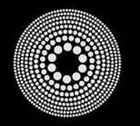
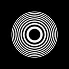
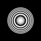
Various zone plates
(a) and (b): Fresnel zone plates consist of white (transparent) zones and black (opaque) zones. The central (first) zone is transparent in the case of (a) and it is opaque in the case of (b). (c): A Gabor zone plate where the transparency changes sinusoidally in the radial direction. (d): A photon sieve where transparent zones of a zone plate are replaced by a lot of holes.
Principle of the zone plate photography: Though the area of the central zone of a zone plate is the same as the area of a pinhole with the same focal length (as described previously there is a focal length even in the case of a pinhole), a brighter image can be realized by gathering up lights diffracted at the outer transparent zones.
By the way a reason why lights passing through large circular areas of the zones can focalize and build up a picture cannot be explained by the rectilinear propagation of a light. This can be explained by diffraction and interference phenomena on the basis of the fact that a light is a wave. In brief, light rays passing through transparent zones and diffracted at the zones are intensified at a focal point and weakened in other places due to the interference of light waves. In order to design the pattern of a zone plate to realize such an optical phenomenon the wavelength of the light and the required focal length of the zone plate should be given first. Then we should decide the number of zones. Usually the number of zones is defined as the total number of transparent and the opaque zones. As the area of each circular zone is same, the width of an outer zone is thinner than that of an inner zone. Therefore, if one makes a zone plate without using a special precision instrument, the number of zones is limited by the working accuracy. It should be also remarked that as the resolution and the chromatic aberration relate with the number of zones as described in the main text, these also limit the number of zones less than a certain number. Moreover, as a zone pattern is determined as a function of a product of the wavelength of the light and the focal length, the pattern is same each other among zone plates with the same value of this product. For example, the pattern of a zone plate for the wavelength of 550 nm (1 nm = 0.000001 mm) and the focal length of 300 mm is the same with a zone plate for the wavelength of 660 nm and the focal length of 250 mm.
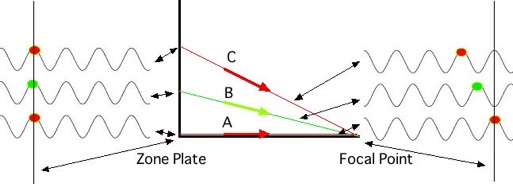
Principle of a zone plate
We consider light waves perpendicularly incident to a zone plate, among which a light ray (A) passes through the central transparent zone and proceeds to the focal point, a (virtual) light ray (B) proceeds from the point in the first opaque zone to the focal point, and a light ray (C) is the ray from the second transparent zone to the focal point. As the length of the path becomes longer in the sequence of A, B, and C, the arrival time of the rays delays in this order. As the (virtual) light ray B delays by a half wavelength at the focal point it weaken the light ray A. On the other hand, as the ray C delays by one wavelength it enhances the light ray A.
Preparing a zone plate: As a pattern of a zone plate is, of course, more complicated than that of a pinhole, it is considerably difficult to shape a zone plate by drilling a thin metal plate as in the case of a pinhole plate. A simple way to make a zone plate is as follows: (1) calculate the zone sizes of the necessary zone plate, (2) draw a large pattern of the zone plate such as several 10 to several 100 times larger than the necessary zone plate, (3) take a negative monochromatic photograph of the above pattern by a film camera so that the size of the zone plate image on the film is the same as that of the necessary zone plate, and (4) use this film as a zone plate.
Taking a zone plate photograph: Though the zone plate is widely utilized for scientific and engineering applications, it is not very popular in the field of the artistic photography and, consequently, the features of the zone plate photography are not well-understood and are, sometimes, misunderstood in this field. It is often said that in comparison with a pinhole photograph far softer photographs are taken by a zone plate. Actually a photograph taken by a zone plate seems very soft. However, it is shown theoretically that the resolution of a zone plate photograph is made higher than that of a pinhole photograph for the same focal length and it can be made higher and higher with increasing the number of zones. Nevertheless, a zone plate photograph untouched as it is taken gives very vague impression. This is due to various features of the zone plate photography, and among them the most important reason is considered to be an effect of a background light. As described previously an image projected on an image plane is formed by interference of light waves diffracted at the zones, but at the zones a larger quantity of light goes straight in the direction of the incident light than the diffracted light. This straight going light makes a halo around the image. From the artistic viewpoint the halo around the image of the photogenic object with a rather small size is said to give a favorable impression of a zone plate photograph. However, the straight going light originating from an ambient light gives a fog over the whole image on the image plane. If the zone plate photograph is taken by a digital camera, it is rather easy to remove the fog by subtracting the nearly uniform “brightness value” corresponding to the background light from that of each pixel. However, as this process is apt to degrade an image quality and the photograph becomes dark, this method is not effective when the ambient background light is very strong. But it can be often mitigated by an HDR processing. These processes will be described in detail in the main text. By the way, though the term, a “background light” is usually used for a light coming from an object other than the targeting one or an ambient light, in this site we indicate, by this term, the directly coming light without suffering deflection at transparent zones of the zone plate.
In the zone plate photography focusing property and chromatic aberration are no less important than the background light. At first a zone plate has a definite focal length and focusing operation seems necessary, especially, to take a closely located photogenic object. Though a zone plate makes a brighter image in comparison with a pinhole, it is still too dark to do focusing through a viewfinder of an SLR and it is necessary to set the position of the zone plate manually by using a calculated value of distance. In general, however, from a practical viewpoint focusing is not necessary except for cases of a zone plate with a very long focal length or with a very large zone number.
Next, there is a problem of the chromatic aberration. As described above a focal length of a zone plate is inversely proportional to the wavelength of the light, which brings a very large chromatic aberration. Moreover, as the permissible range of a position of the focal point due to the chromatic aberration is inversely proportional to the number of zones, it seems that a colorful object cannot be taken with high resolution by a zone plate with a large zone number. Though even a usual zone plate camera with a rather short focal length (f=50 - 100 mm) and a small number of zones (10 ~ 20 zones) cannot cover the whole wavelength range of the visible light (400 - 700 nm), color of a photograph by the zone plate camera does not look too unnatural. However, if one decomposes this photograph into three images of the RGB channels, one will find that only the image in the G channel (a light of f=550 nm is a green light!!) is in focus and images in the other channels are out of focus. A reason why a zone plate photograph looks rather natural under such a situation may be explained by the fact that the shape of the image of the photogenic object is expressed by a sharply focused light and the color of the object is expressed by superposition of the visible lights in all the RGB channels. To take a zone plate photograph, therefore, the light with a wavelength determining the focal length should be relatively strong in a measure within the viewing frame.
Applications of zone plates: A lens and a mirror reflector are very useful optical components and used extensively for various applications. On the other hand, lensless optical systems such as a pinhole or a zone plate are not conveniently used as a lens or a mirror reflector because of various constraints associated with them. However, such lensless systems have two favorable features, (1) no material is indispensable on a pathway of the light for refraction or reflection, and (2) the weight of the system is very light even when it is very large. By utilizing the features some lensless optical systems have been made or projected to develop. The first feature is very important to apply a zone plate to an optical system for lights other than visible lights such as infrared, ultraviolet lights, or X-ray, gamma-ray, and various particle beams, and actually the zone plate optical systems are taking active parts in the field of experimental physics. This is because there is no appropriate optical material as a lens for these lights or particle beams. For these objects an above-described zone plate made of a film cannot be used, of course, and micro-fabricated metal or ceramic zone plates are used. The second feature is extremely advantageous for a space telescope placed on a satellite orbit. As a planning a space telescope with a focal length of several 10 km and diameters of a sensor and a zone plate are more than several meters is considered. It is almost impossible to construct a telescope of glass lenses or mirrors of the same size because it will become too heavy. However, it seems still considerably difficult to realize such a large space telescope as it is necessary to control such a large zone plate system within an accuracy of millimeters.


(a)
(d)
(c)
(b)