Atelier Bonryu(E)
zone plate photography


Atelier Bonryu(E)
zone plate photography


Laboratory: Zone Plate Photography
Taking Zone Plate Photographs
- Finishing with Unblurred Photograph, Revisited -


Finishing with a unblurred zone plate photograph: An image taken by a zone plate is by far clear than a pinhole photograph in principle, but a taken photograph usually looks very soft and clouded. As this is due to the background light peculiar to the zone plate photograph this effect can be reduced to make a photograph unblurred by reducing uniformly the level of the brightness of the photograph by a certain value. This fact has already been described. Though this method has been considerably effective for a case under a favorable light condition, it is not necessarily applicable to any case due to larger non-uniformity of a background light. The best way to make a photograph unblurred is to remove all the contribution of the background light itself. You may be suspicious on the fact but it can be carried out if not perfect.
Origin of the background light: Let's consider what is, after all, the image projected on a screen by a zone plate. It must be a superposition of an image due to the diffracted light and an image due to a straightly traveling light. The image due to the diffracted light is the image that we have been calling as the “image by a zone plate” up to now. Though you may consider that all the incident lights contribute to form an image by the diffraction when reading the explanation on the zone plate imaging, it is necessary to fulfill the condition of the coherency for lights to form a zone plate image and other incoherent lights travel straightly to the screen to become background lights. As the image due to the straightly traveling light is the one produced by a light passing through the transparent parts of the zone plate, it is the same image produced by a pinhole whose radius is the same as the radius of the outside circle of the outermost zone of the zone plate. As a matter of course, because the area of such a pinhole is the sum of areas of all the transparent and opaque zones, this area is twice as large as the area where the straightly traveling light passes through in the case of the zone plate. Therefore, the quantity of the straightly traveling light in the case of the zone plate is half of the straightly traveling light in the case of the pinhole with the same radius. In brief on the screen two images of the object, that is, the image due to diffracted light and the pinhole image (with the half brightness) are superposed. It should be noted that the radius of this pinhole is far larger than the optimum radius of the pinhole of the same focal length. For instance, in the case of the example we show later, the radius of the zone plate with 29 zones designed for the light wavelength of 550 nm and the focal length of 200 mm is 1.8 mm, but the optimum radius of the pinhole is only 0.33 mm for the same focal length. The image is formed actually by such a large radius as 5.5 times the optimum radius. For this reason the image due to the straightly traveling light through the transparent zones is a very vague "image" which can be scarcely recognized even as an image. Almost all component of the background light observed in a zone plate photograph is considered to be this pinhole image. By the way, strictly speaking, the spatial distributions of light intensities due to a pinhole and a zone plate composed of many annular zones are different even if the radii are the same, but the light beams diverge during traveling to the screen and it does not make much difference.
A method to remove the background light: Previously we described a method to remove the effect of a background light by subtracting a constant value of brightness from all over a photograph. Now we know that the origin of the background light is the image due to the corresponding (very large) pinhole and, therefore, we can conclude that the background light can be removed more strictly by subtracting the values of brightness due to the pinhole image. For this purpose we made a pinhole with a same radius as the zone plate and took two photographs by using the zone plate and the corresponding pinhole and then subtracted the values of the brightness of the pinhole image from the zone plate image by regarding that the pinhole image is the background light of the zone plate photograph. As we take two images for a single photograph, two images should be taken at the same place and at the same time as long as possible. Consequently, we made a device, a pinhole plate on the top of a pipe and an attachment for a zone plate in front of the pinhole. By attaching the zone plate we take a zone plate photograph and by quickly retracting the zone plate we take a pinhole photograph (Fig.1). Firstly we insert the zone plate shown in Fig.1a before the pinhole and take a zone plate photograph, and then we retract the zone plate quickly and take a pinhole photograph by the pinhole with extremely large radius.
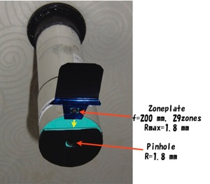
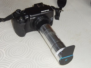
Figure 1 A device for zone plate photography combined with a pinhole for removing a background light. (a) A figure showing the device from which the zone plate is retracted, (b) A figure of a camera with the device.
(a) (b)
Image Processing Softwares: As we are not using a film camera but a digital camera, it is rather easy to combine the two photographs to make a zone plate photograph without a background light. For this purpose we can carry out an appropriate calculation for each RGB channel of each pixel by using basic functions of some image processing softwares, but there also come in softwares which can process such operations for all the pixels and channels of a photograph in the gross. Here we describe the processing method by using PixelMath or ImageJ softwares. By the way these are free softwares.
Image Processing: We name a photograph taken by a zone plate as “Image1” and one taken by a pinhole as “Image2”. If we carry out the calculation, Image=Image1-Image2, a new photograph “Image” is obtained which is the zone plate photograph from which the pinhole image is removed. Hereat, the brightness of Image2 is twice of that of the background light as described previously. Therefore, in actuality, the equation, Image=Image1-0.5xImage2, should be employed. It should also be noted that the ranges of the RGB values of each pixel are from 0 to 255. If a value becomes negative then it is replaced by 0 and if a value becomes more than 255 then it is replaced by 255. As it is very difficult to prepare a pinhole, radius of which is exactly same as the radius of the zone plate, it is necessary to adjust the multiplication factor appropriately. In summary, necessary equation for the image processing is as follows, Image=a(Image1-bxImage2)+c where a, b, and c are appropriately chosen numbers. In our experiments rather good results were obtained by choosing the values as a=1.0~2.0, b=0.3~0.5, and c=0. When we use the “Calculator” function of PixelMath the above calculation can be carried out at one step but there is a limiting size of a photograph for saving the result. On the other hand in ImageJ there is no such limitation for a practical use but we must install a plugin named "Image Calculator Plus" beforehand. Moreover, the above operation is carried out in two steps by ImageJ. As for the variables, Image1 and Image2, the softwares, ImageJ and PixelMath employ the variables, i1 and i2, and Source1 and Source2, respectively. Though we have not searched other image processing software with similar functions it is considered that there may be some good softwares because these functions are rather basic ones.
Examples: The followings are photographs which are obtained by removing background lights by using the method described above. Though there is still room for improvement it is clearly shown in all the photographs that background light is removed considerably. As a matter of course, if there is a very strong and small light source in the object a ring-shaped image of background light remains. In all the photographs, we employ a zone plate with a focal length of 200 mm and a zone number of 29, which results in radius of 1.8 mm, and a pinhole with a radius of a little larger than 1.8 mm.


(Slide show)