Atelier Bonryu(E)
pinhole photography


Atelier Bonryu(E)
pinhole photography

Laboratory: Pinhole Photography
Taking Pinhole Photographs - Remark
Remark#4: Optimum Pinhole Diameter
Huygens’ Principle: In order to understand why there is an optimum value for a pinhole diameter, we consider the mechanism of the pinhole phenomenon by using a simple model. We analyze the problem on the basis of the famous Huygens’ principle (1690, Holland, Christiaan Huygens, 1629 -1695). It should be noted that, as by the original Huygens’ principle the diffraction phenomenon of a light wave cannot be explained properly, the principle of Huygens and Fresnel is used for the analysis, where the effect of the interference is taken into account.
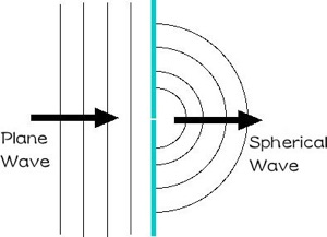
According to the Huygens’ principle, secondary spherical waves are emitted from points on a surface wavefront of an incident light wave and the envelop of the secondary waves form a new surface wavefront (Fig.1). Therefore, a light wave with a flat surface (a plane wave) remains a plane wave without change in every point.
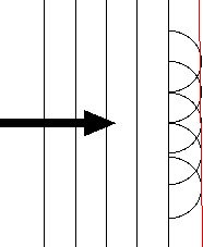
Fig.1: Huygens’s principle
A new surface wavefront is formed by an envelope (a red line) of secondary waves each of which is emitted from a point on a previous surface wavefront as a source.
Fig.2: Small pinhole case
When a diameter of a pinhole is extremely small a light of a plane wave passing through the pinhole becomes a spherical wave.
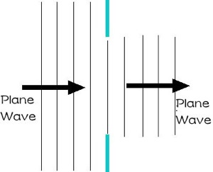
Fig.3: Large pinhole case
When a diameter of a pinhole is very large a light of a plane wave passing through the pinhole remains a plane wave.

(a)
(b)
(c)
(d)
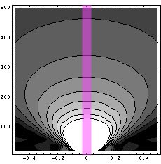
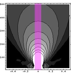
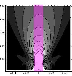
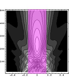
Fig.4: Dependence of diffracted light intensity on pinhole size (slit width)
A slit is located on the horizontal axis and the incident light comes from beneath. The pink bands denote the light beam without the diffraction phenomenon. Sub-figures (1), (b), (c), and (d) show the cases with the slit width d=0.05, 0.1, 0.15, and 0.3 mm, respectively.
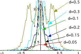
From Fig.4 it is not difficult to understand that the diffracted light diverges rapidly in the case of a narrow slit as d=0.05 mm but by using a wider slit as d=0.15 mm the width of the light beam is confined within the width of the slit at the distance of 100 mm from the pinhole plane. We made calculation of the distribution of the light intensity at the focal plane for the case of the slit width of d=0.15mm (Fig.5). It is also clearly seen that the minimum beam width is attained for d=0.15 mm.
Fig.5 Distribution of the light intensity on the focal plane (f=100 mm) for different slit widths, d=0.05, 0.1, 0.15, and 0.3 mm.
However, when the plane wave encounters a wall with a very small pinhole, a new secondary spherical wave is emitted from the pinhole as a point source (Fig.2). The new wavefront is that of the secondary wave itself because the pinhole is very small and the source is considered as one point without an area. By applying the Huygens’ principle to this spherical wave, it is understandable that the light wave after passing through the pinhole remains still a spherical wave in every point. In this case the ”pinhole phenomenon“ cannot be observed because the light wave does not go straight to the traveling direction of the incident plane wave.


This equation is the same as that in the main text. There are more other formulas with different coefficient but differences are not essential by considering the difference due to the wave length of the light adopted for the calculation.
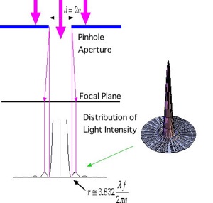
Fig.6 Determination of the optimum pinhole diameter
Determine the pinhole diameter from the diameter of the central circle of the distribution of the light diffracted by a circular pinhole.