Atelier Bonryu(E)
zone plate photography


Atelier Bonryu(E)
zone plate photography

Laboratory: Zone Plate Photography
Theories of Zone Plate Photography
- Diffraction and Interference of Light -

Light waves diffract and interfere: We briefly explain the principle why an image of a photogenic object is formed on an image plane by a zone plate. As described above the zone plate imaging is not a consequence of refraction or reflection phenomena. For the zone plate imaging we make use of diffraction and interference phenomena arising due to the fact that a light is a wave. The lower left animation shows that a water wave which comes from the left downside propagates circularly after passing through a thin slit on a yellow shielding wall. The phenomenon observed in this animation where a wave propagates even behind a shielding wall is called diffraction. As a light is also a wave, we can see the similar diffraction phenomenon in the case of a light. However, there is a condition whether the diffraction phenomenon can be clearly observed or not. When the wavelength is far smaller than the size of a slit a quantity of the diffracted wave is small, which means that majority of the light propagates in the forward direction. The lower right animation shows the motion of a water wave where the width of a slit is larger than the wavelength. In the case of a light wave passing through a pinhole or a zone plate the wavelength is by far smaller and almost all lights go straight in the forward direction and only a small quantity of the light is diffracted. A zone plate utilizes this small quantity of the diffracted light.
Diffraction of a water wave (a narrow slit case)
A water wave passing through a slit small in comparison with the wavelength expands as a circular wave.
Diffraction of a water wave (a wide slit case)
A water wave passing through a slit large enough in comparison with the wavelength propagates in the forward direction (slit not shown).
Making use of diffraction and interference phenomena: If the diffraction phenomenon is utilized properly the diffracted light wave as well as the rectilinearly propagating light wave form a bright image cooperatively on the image screen and a bright lensless optical system is realized. However, if one is to use lights diffracted at holes or slits on a light-shielding wall disorderly, an image of the object cannot be formed on the image screen. It is because the light observed at a certain point on the image screen consists of various diffracted lights due to different original lights coming from various directions. Consequently in order to build up an image we should intensify lights at the necessary points and reduce unnecessary ones by making use of the interference phenomenon of light waves. As a matter of fact, for the explanation of the diffraction phenomenon itself the concept of interference is already included but for simplicity we consider the diffraction and the interference phenomena separately. Because a light is a wave it takes positive values and negative values with passing time. When at a certain point one observes lights coming from two directions, i.e., one of which has a positive value and the other has negative value, these light waves compensate each other and the overall wave amplitude becomes small. If both the waves have positive values or negative values at the same time these waves build up each other and the overall amplitude becomes large. This phenomenon is the interference of waves. The upper right animation shows that the water wave running through a single wide slit (not shown) propagates in the forward direction with a small divergence due to the interference phenomenon. On the other hand in the lower left animation the interference phenomenon is more clearly observed for water waves passing through two slits.
Interference phenomenon of a water wave (two slits)
Circularly propagating water waves passing through two slits interfere each other.
Focusing of a light wave by a zone plate
Amplitude of a light wave coming from beneath becomes large near the focal point by a zone plate.


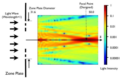
By the way, how large is the realistic optical system which corresponds to the above calculated system with a wavelength of 1.0, the number of zones of 5 and a focal length of 90.0? As the realistic zone plate is usually designed for a visible light with a wavelength of 550 nm (=0.00055 mm), the focal length of 50.0 employed for the above calculation corresponds to 50.0 (0.00055/1) mm = 0.0275 mm, and the radius of the zone plate (the outer radius of the outermost transparent zone) is 0.01738 mm, by which a light is focused within a small circular region with a radius of about 0.001 mm. This system is extremely small but it is considered that if one can construct such a small system one will see similar results as the above calculation.
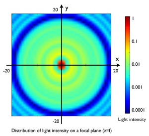
Two dimensional distribution of light intensity on the focal plane
The light converges at the focal point and concentric intensity distribution around the focus is seen.
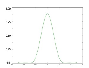
Intensity distribution along x-axis on the focal plane
This figure shows the one dimensional intensity distribution along the x-axis of the left figure.


(English Edition)
Soft Light and Shadow
<=======(Japanese Edition)=======>
Lensless Photography
by Rings of Light
(Volume of Stones)
Lensless Photography
by Rings of Light
(Volume of Birds)
Lensless Photography
by Rings of Light
(Volume of Flowers)
Complete Guide to
ZonePlate Photography