Atelier Bonryu(E)
pinhole photography


Atelier Bonryu(E)
pinhole photography

Laboratory: Pinhole Photography
Applications of Pinhole Photography
- Pinhole Mirror(1) -
Observation of the Sun: As a light through a pinhole is weak and an image is dark in contrast with the case of a glass lens, mainly the sun has been an object of the observation by using the pinhole phenomenon. As long as it is used for the observation of the sun the light intensity through the pinhole is sufficient but the resolving power attained by a pinhole is weaker than that by a lens. The resolving power of a pinhole telescope optimized with respect to the focal length is described in (*4). For example, the photograph of sunspots in the book “Observation of Sunspots” by Ichiro Shimizu, et al. was taken by using a pinhole telescope with the focal length of 2 m and the pinhole diameter of 1.8 mm, where only vague sunspots can be seen with difficulty. Though it was not explicitly described in the book the diameter of the solar image and the relative resolving power must be 18 mm and about 25, respectively. Therefore, the number of pixels of a corresponding digital photograph along the diameter of the solar image is only about 25, which suggests that it is indispensable to use a pinhole with a longer focal length for clearer observation of sunspots.
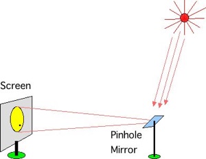
If one use a pinhole telescope with the focal length of 20 m and the optimized pinhole diameter of 5.2 mm, the diameter of the image of the sun and the relative resolving power are 186 mm and 70, respectively, and a distinct picture of the image of the sunspots will be attained. There are, however, several problems to be solved to make such a pinhole telescope. Firstly, the light intensity at the image screen will be reduced with increasing focal length. It may be a small problem as long as the telescope is used for the observation of the sun. However, as the light intensity decreases in inverse proportion to the squared distance, it may be still a problem. In the second place it is rather difficult to stick up the telescope pointing to the sun because the telescope is very long. This problem is solved by making the path of the light to a horizontal direction by using a mirror. In this case we must align the system of the mirror, the pinhole plate, and the image screen so that the image of the sun stands still on the image screen. Otherwise the solar image moves at the speed of about 1.5 mm/sec on the image screen because the sun moves at the angular speed of 2.5 degree per minute on the ecliptic. This problem can be solved rather easily by using a pinhole mirror because the pinhole is located closely on the mirror.
Pinhole Mirror (*6): A pinhole mirror is a surface mirror on which a pinhole plate is affixed. An incident light through the pinhole is reflected at the surface of the mirror and goes outward through the pinhole again. Articles on observations of sunspots by a pinhole mirror are found in several websites such as the site by Barry Malpas. A pinhole mirror is considered as the same device as the “pinhead mirror” introduced in the article “The Pinhole Camera” by Matt Young. The pinhead mirror is a very small mirror which works as a pinhole, because the small mirror itself can be considered as a pinhole. It should be remarked that there is no body tube in the “pinhole mirror telescope” unlike the pinhole telescope. This means the image screen is exposed to the luminosity of the surroundings and, therefore, the pinhole mirror telescope can be used only for the observation of an extremely bright object such as the sun.
By the way Matt Young described in the article about the discovery of the pinhead mirror. It was described that Thomy Nilsson, a vision scientist discovered the pinhead mirror in 1986 and he asked whether it was an undiscovered imaging device. It was also described that three letters in Lasers and Optics (1982, p.12) suggested that the pinhead mirror had been invented before and an example by Donald O’Shea was mentioned. I have not read the above letters in Lasers and Optics but I have found that Robert W. Wood, the famous US physicist whom I describe in the pages of a zone plate photography, an infrared photography, and an ultraviolet photography of this site, had already described on the pinhole mirror in his book “Physical Optics, the 3rd edition” (1934 Macmillan, Reprint: 1988 US Optics Society), p.272. Though there is not a description on the pinhole mirror in the 1st and the 2nd edition of “Physical Optics”, it might be possible that he knew the pinhole mirror before the publication of the 3rd edition because he was interested in the lensless photography, and he took zone plate photographs and submitted a paper concerning them. In the 3rd edition of his book he introduced the formula of the optimized pinhole diameter derived by Lord Rayleigh and described a concrete design of a pinhole mirror as follows. At first by using a pinhole with a diameter of 15 mm we project an image of the sun on a wall located, for example, 200 ft (about 60 m) apart from a window or a door through a dark corridor. As in this case the optimum pinhole diameter is about 6 mm the diameter of 15 mm is too large and the resolution power is degraded considerably. However, as the light intensity at the image plane is 6 times larger than the case by the pinhole of the optimum diameter, the sun can be observed in a rather light room. Wood described that if a very dark corridor is available and the image plane is sufficiently dark a striking result will be attained by using a pinhole with an optimized diameter. Moreover, it was mentioned that an elliptic pinhole might be better for the shape of the pinhole used for the pinhole mirror because as for the shape of pinhole seen from the image plane a perfect circle is better.
Observation of sunspots by a pinhole mirror