Atelier Bonryu(E)
infrared photography


Atelier Bonryu(E)
infrared photography


Laboratory: Infrared Photography
Remark #5 Sensitivity of a Sensor and Signal from a Channel
Importance of Post-Processing in Infrared Photography: In order to bring an infrared photograph to completion even whether it is a monochromatic or a color photograph the post-processing is extremely important. As we cannot perceive the infrared light, colors of an image detected by the sensor of the camera should be changed to perceivable colors. Suppose we take a photograph of a red apple. When the light ray reflected at a point on the surface of the apple reaches the sensor of the camera and information concerning the incident light ray is recorded. Generally speaking, the light ray does not correspond to a single wavelength light but is a flux of lights with extensive range of wavelength. Within this extensive range the infrared light is contained as a matter of course. In a camera this light ray is decomposed to three light rays by a Bayer filter and three signals corresponding to these light rays are recorded. When we look at the output image of the camera, as our eyes work similar to the camera, the color of a point constituting the image is transferred to our brain as three kinds of signals as in the case of the camera and create a “feeling (quale) of a color” in the brain.
If the three signals are derived from the incident lights with wavelength within the range of visible light there is no problem concerning the correspondence between the colors of object and reproduced colors in the brain. However, if an information by the infrared lights is included in the signal(s) no feeling of an infrared light is created in our brains because our brains have no experience to perceive the infrared light. Therefore, it is necessary to convert a color of infrared light to a perceptible color of a visible light. The color reproduced by this processing is the “false color”. Even for a color corresponding to the visible light two people might have different feelings (qualia) and when two people look at a red apple we cannot know whether the two people have the same feelings in their brains. However, it does not cause a trouble because both of them think that the color they perceive is the red color. Because of acquired qualification among many people the correspondence between “the color of an object being seen” and “the color reproduced in the brain” is almost same.
What is Color: Unlike the visible light we can assign any color to an image of an infrared photograph because we don’t share common view on the color of the infrared light. In the case of an infrared color film the correspondence between the wavelength of the incident light and the expressed color is determined when the film is produced. Though the color assignment is changed a little by choice of filters and development process the color corresponding to the wavelength of the incident light is basically determined from the start. On the other hand in the case of the digital infrared photography the incident light is divided into R-, G-, and B- channels and the colors corresponding to these three channels are assigned afterward. Originally the signals from these R-, G-, and B- channels represent the colors of red, green, and blue within the wavelength range of the visible light but in the wavelength range of the infrared light, the signals from the R-, G-, and B- channels do not have relations with the color of the visible light, red, green, and blue. Therefore, in order to understand the false color well we need to understand the sensitivity of the sensor and the performance of the filters. In the following the sensitivity of the sensor of a digital camera and the performance of filters used for the infrared photography are briefly explained.
Sensor of Digital Camera: A sensor of a digital camera is usually made of CCD (Charge Coupled Device) or CMOS (Complementary Metal-Oxide-Semiconductor). As it is not the purpose of this web site to explain the features or performances of these devices we skip the detailed explanation of them. However, it should be emphasized that the sensors made of CCD or CMOS can detect light with wavelength of very wide range in comparison with a human eye as shown in Fig.1-3. Generally though such data of a sensor a s used for a specific camera are not published by a manufacturer the KAC-00401 CMOS sensor by Kodak is published, which was used in several digital camera. In this web site we consider the problems of the sensitivity of a sensor by taking into account of the KAC-00401 CMOS sensor. Though a sensor of a digital camera advances very rapidly sufficient information is obtainable for the basic understanding of the sensor of a digital camera.
At first, we show the wavelength dependence of the sensitivity of the main body of the KAC-00401 and that of the KAC-00401 sensor with Bayer filter (Fig.R5-1). Bayer filter is a set of a filter array composed of 2 x 2 filters with 1 red, 1 blue, and 2 green filters, which is invented by Bryce Bayer of Eastman Kodak in 1976 and now used for a sensor of a digital camera as a standard filter. Recently, to cope with a false color associated with a spatially high frequency pattern appearing with increasing number of pixels different types of “Bayer filters” with higher basic periods such as 3 x 3 or 4 x 4 and with irregularly located patterns are devised.
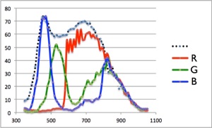
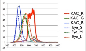
Figure R5-1 The dependence of the sensitivity of the KAC-00401 sensor on wavelength. The dotted curve is the sensitivity of the main body of the sensor without a UV-IR cut filter.
Figure R5-2 The dependence of the sensitivity of the KAC-00401 sensor (solid line) and the human eye (dotted line) on wavelength.
Figure R5-2 shows the dependence of the sensitivity of the KAC-00401 sensor on the wavelength when a UV-IR cut filter is placed in front of the sensor. As the performance of the UV-IR cut filter used for a camera is unknown it is assumed that a B+W 486 UV-IR cut filter is placed. Though the main body of the sensor detects a light with the wavelength of 350 ~ 1000 nm detectable range of the sensor with the UV-IR cut filter narrows to 400 ~ 700 nm. For the sake of comparison the sensitivities of the human eye, i.e., L cone cell (R channel), M cone cell (G channel), and S cone cell (B channel) are drawn on the same graph. These figures clearly show that the detectable wavelength range of CMOS detector is far larger than that of the human eye.
Bayer Filter: At present almost digital cameras use the Bayer filter. The conversion of a camera for the infrared photography is to remove the IR cut filter placed in front of the sensor. In this regard there might appear a question. The question is: even if the IR cut filter is removed the intensity of the infrared light which reaches the sensor passing through the Bayer filter may be very small. This question is cleared up we see the graph of the dependence of the sensitivity of the KAC-00401 sensor on the wavelength (Fig.R5-1). This is because the transparencies of all the three filters, i.e., R-, G-, and B- filters become large in the infrared region again.
Then we would like to know effects of other filters on the sensor with the Bayer filter. Figure R5-3 shows the transparencies of an IR cut filter B+W 486, a sharp cut filter SC68, IR transparent filters IR72, IR76, IR80, IR84 from the left to the right. For the filters SC68, IR76, and IR84, the output intensities of R-, G-, and B- channels are shown in Fig.R5-4, -5, -6.
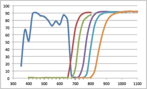
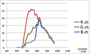
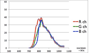
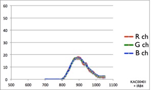
Figure R5-3 The dependence of the sensitivity of the UV-IR cut filter and the IR transparent filters on wavelength. From the left to the right: the UV-IR cut filter B+W 486, the sharp cut filter SC68, the IR transparent filters IR72, IR76, IR80, and IR84.
Figure R5-4 The output curves of the R, G, and B channels of the KAC-00401 sensor with the sharp cut filter SC68.
Figure R5-5 The output curves of the R, G, and B channels of the KAC-00401 sensor with the IR transparent filter IR76.
Figure R5-6 The output curves of the R, G, and B channels of the KAC-00401 sensor with the IR transparent filter IR84.
In the case of the KAC-00401 sensor it is clearly seen from Fig.R5-6 that the IR84 filter blocks the light with the wavelength shorter than 800 nm and, moreover, the output curves from the R, G, and B channels are almost same. For this reason the photograph taken by using this filter cannot be processed to a colorful photograph. On the other hand, by using the sharp cut filter SC68 the output curves from the R, G, and B channels are considerably different each other, and the colorful photograph can be processed.