Atelier Bonryu(E)

zone plate photography


Path of obliquely incident light waves

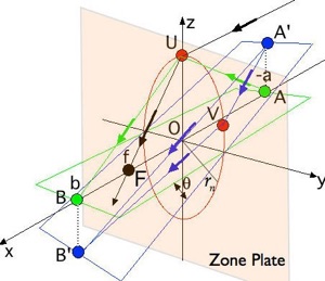
   A zone plate is located on yz-plane (x=0) and the optical axis is the same as x-axis.  The n-th zone (transparent) is shown by a red circle.  Light waves from infinity arrive at the focal point F passing through an arbitrary point U on the n-th zone.  Light waves from a point on the optical axis at a finite distance a from the zone plate pass through an arbitrary point on the n-th zone and arrive at the point B in phase. Light waves from an off-axis point A’ pass through an arbitrary point on the n-th zone arrive at a point B’ in phase.

Laboratory Zone Plate Photography

Principle of Zone Plate Photography

- Remark -

Remark#3: Image Formation by Obliquely Incident Light

Obliquely incident light: In this page it is shown that even an obliquely incident light converges to a point on an image plane.  We consider a zone plate as shown in the right figure.  When a light from a point source at infinity is perpendicularly incident upon the zone plate the light converges to the focal point F via each transparent zone.  In the figure this light is deflected at a point U of the n-th zone and converges to the focal point F (a black line).  If the point source is located at a point A away from the zone plate by a finite distance a an image of this point source is formed at a point B (distance b from the zone plate).  The green line AUB is one of  representative light paths from A to B.  If we put a point source at a point A’  just above the point A, an image of the point source A’ is formed at a point B’ just below the point B and on an extension of a straight line A’O.  We assume the angle
between the lines AB and A’B’ is small.
 
Difference of path-lengths: This is proved as follows.  First we calculate the path-length A’VB’ of the light emitted from the point A’ where V is an arbitrary point on the n-th zone.  Then the difference between the length of A’VB’ and the path-length A’OB’ is calculated.  If the difference is
it can be said that the point B’ is the image of the point A’.  We show the calculation as follows.


As just described the difference of the path-lengths between the central path A’OB’ and the path A’VB’ is
and therefore the point B’ is the image of the point source ZA’.
 
next=>ZP_Salon_R.4.html../atelier_bonryu/PH_Salon_1.2.htmlshapeimage_2_link_0
next=>ZP_Salon_R.4.html../atelier_bonryu/PH_Salon_1.2.htmlshapeimage_3_link_0

Home    Content    Gallery    Laboratory    About This Site    About Me    Link    Contact    Site History    Bonryu Club     Site Map