Atelier Bonryu(E)
zone plate photography


Atelier Bonryu(E)
zone plate photography


Laboratory: Zone Plate Photography
Taking Zone Plate Photographs
- Remark -
These results are rather pessimistic for photographing by the sub-focus. However, from the figures it is expected that the sub-focus may become useful for a larger zone number, and it is tad too early to give up to use the sub-focus. Especially the first order sub-focus of the zone plate with a long focal length looks hopeful. As shown in the main text the actual experience of photographing by using the sub-focus encourages this conclusion.
Remark#7: Sub-Focus


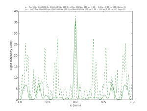
The distribution of light passing through the zone plate with the focal length of 100 mm and the zone number of 5. The solid line shows the distribution on the main focal plane (f), the broken line shows the distribution on the sub-focal plane (f/3).
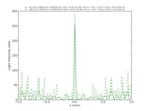
The distribution of light passing through the zone plate with the focal length of 100 mm and the zone number of 15. The solid line shows the distribution on the main focal plane (f), the broken line shows the distribution on the sub-focal plane (f/3).
Above figures show distributions of the light on the main and sub-focal planes when parallel light beam enters a zone plate with the focal length of 100 mm. The left figure shows the result for the case of 5 zones and the right for the 15 zones (same as the figure in the main text). As the figure in the main text is for the region near the optical axis the resolution of the image projected on the sub-focal plane seemed rather good. But at the region far from the optical axis the intensity of the background light becomes extremely large and the resolution is expected to be deteriorated considerably. Especially in the case of 5 zones the intensity of the background light becomes very large and the sub-focus cannot be used for photographing. To see the distribution of light more comprehensively we show the 2-dimensional distribution of light intensities on the plane including the optical axis and the plane perpendicular to the optical axis.
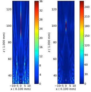
The distribution of the light on the plane including the optical axis (x=0).
The zone plate is located down below and the number (z) is the distance from the zone plate. Both the figures are for the focal length of 100 mm. The left figure is for 5 zones and the right figure for 15 zones. The light intensity is strong at z=100 mm and 33 mm on the optical axis, but in the left figure the light intensity is very strong at z=33 mm even far from the optical axis.
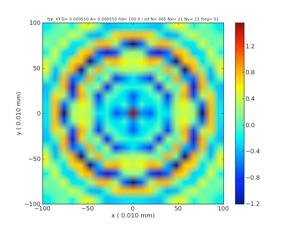
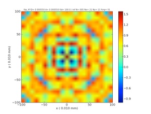
The distribution of light on the focal planes (the focal length of 100 mm and the zone number of 5).
The left figure shows the distribution on the main focal plane (z= 100 mm) and the right for the sub-focal plane (z=33.33 mm).
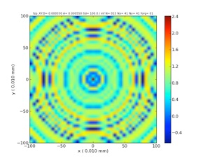
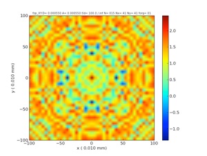
The distribution of light on the focal planes (the focal length of 100 mm and the zone number of 15).
The left figure shows the distribution on the main focal plane (z= 100 mm) and the right for the sub-focal plane (z=33.33 mm).